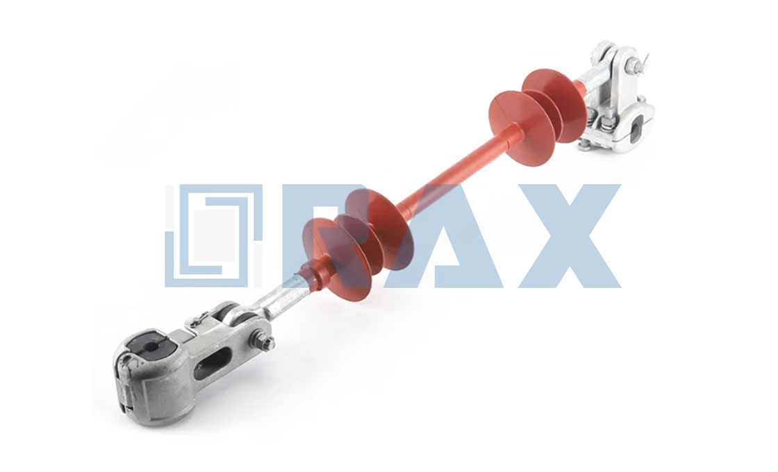
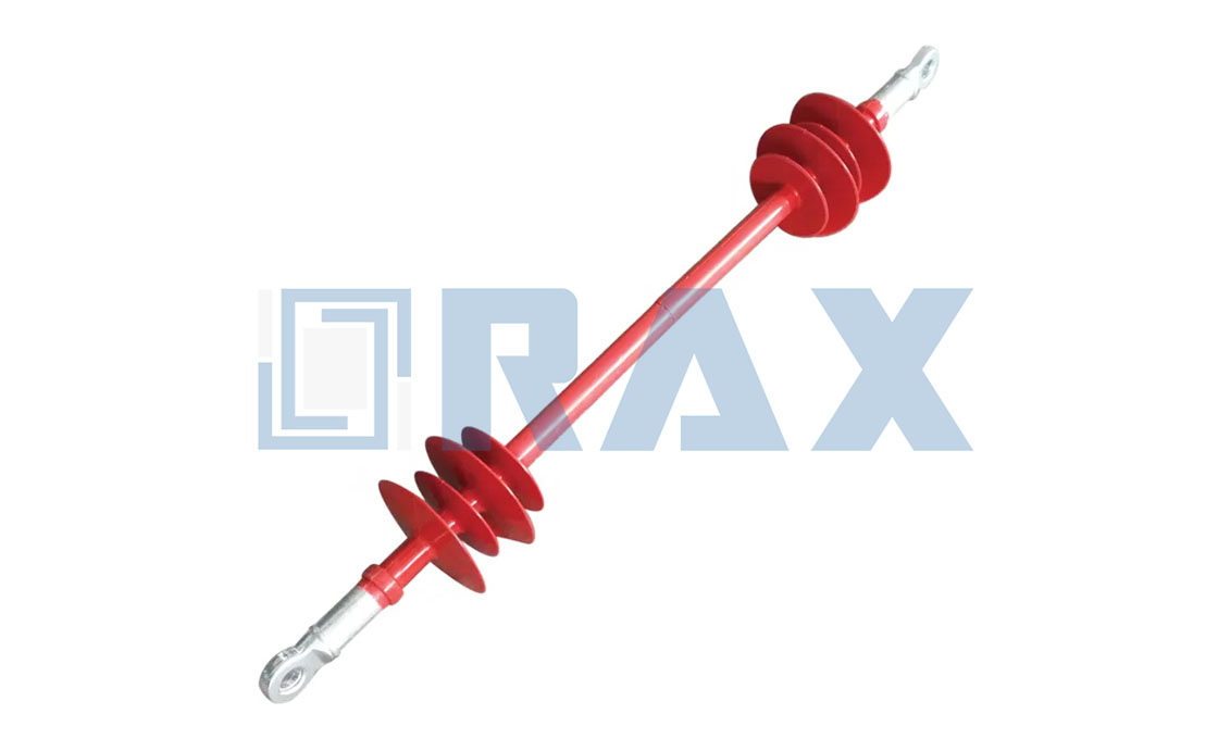
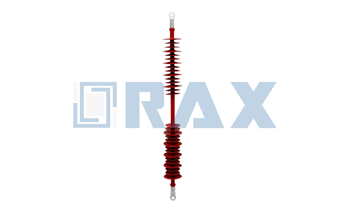
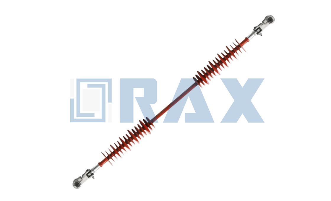
Interphase Spacer
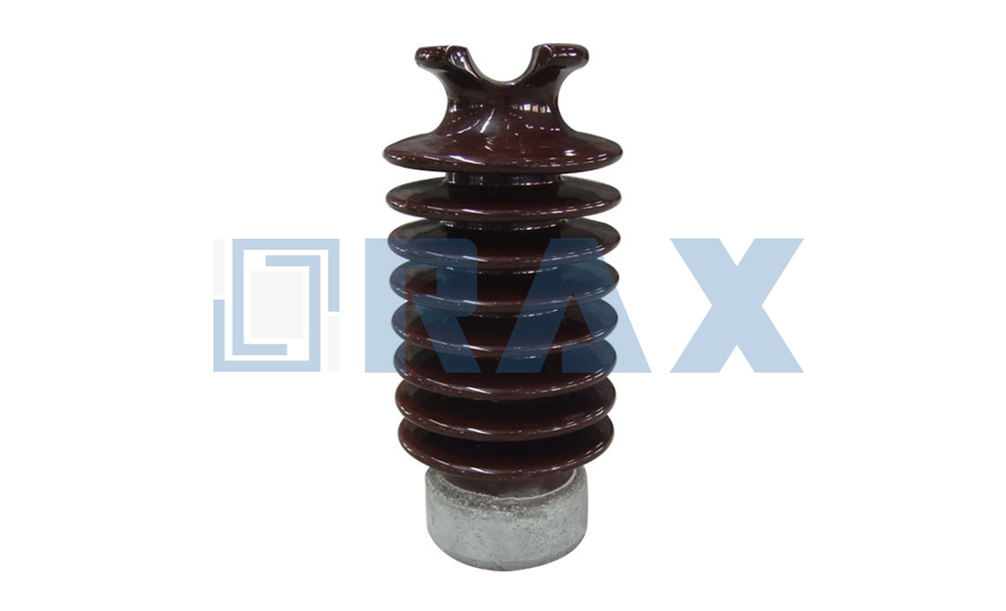
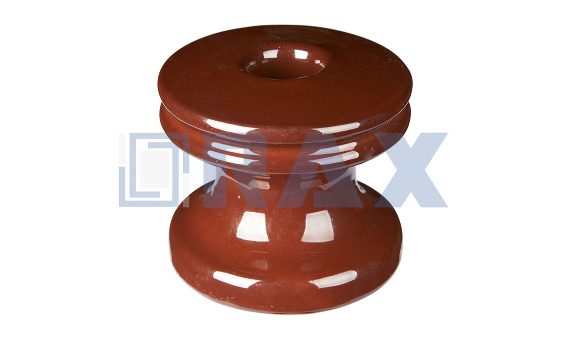
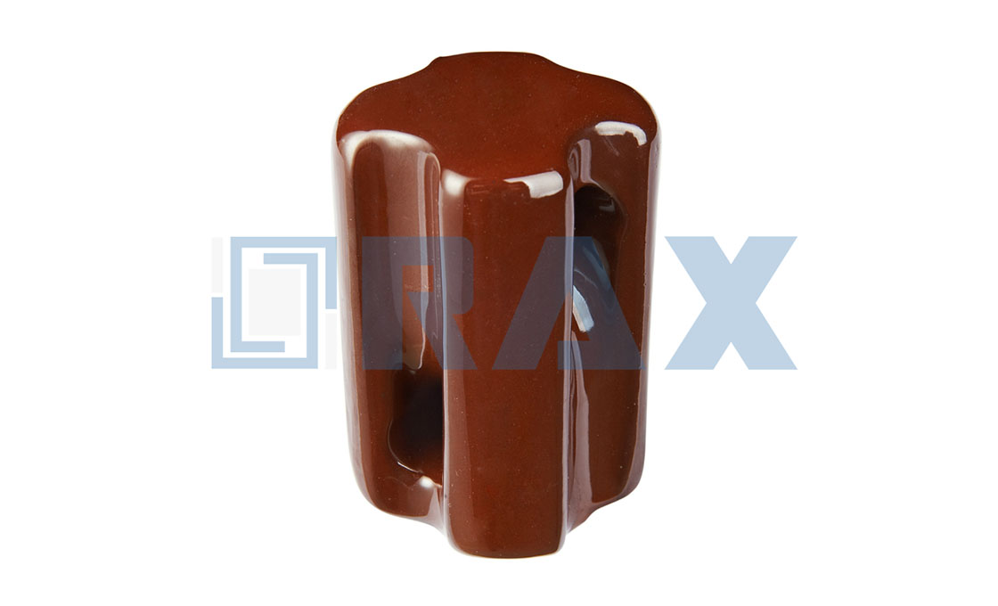
Interphase spacers are specialized insulators designed to prevent mid-span flashovers in power transmission lines. These anti-galloping devices come in three main types: segmental flexible, integrated flexible, and stiff interphase spacers. The structure consists of composite materials with metal end fittings and clamps, featuring a fiberglass rod core that’s larger in diameter than typical line insulators to prevent deformation under mechanical stress.
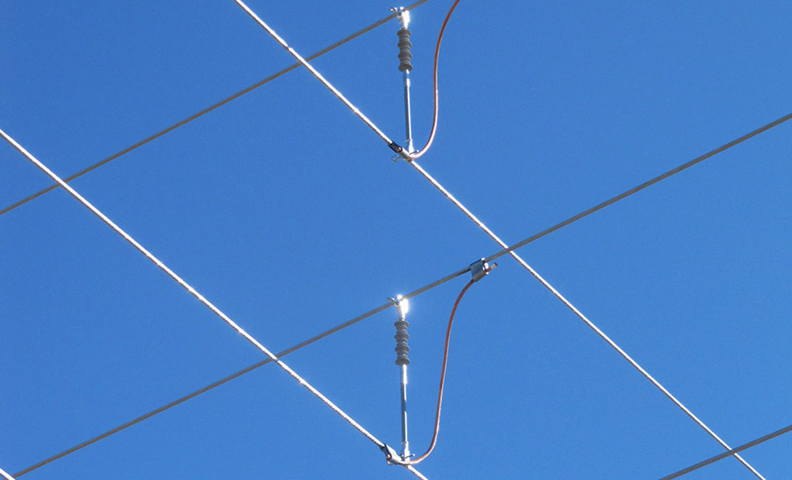
Interphase spacers function by mechanically connecting conductors of different phases to maintain proper separation and prevent phase-to-phase contact. When installing interphase spacers, they are typically positioned asymmetrically along the span to avoid standing waves, with specific placement depending on span length and voltage requirements. These devices work effectively with various conductor configurations, including single, twin, and bundle conductors, making them versatile for transmission line applications from 66kV to 500kV systems.
Key Features:
• Field-adjustable spacer length for specific project requirements
• Composite design for superior vibration absorption
• Dual compression and tension load resistance capability
• UV-resistant and lightweight construction
• Compatible with multiple conductor bundle configurations
• Enhanced mechanical properties for galloping control
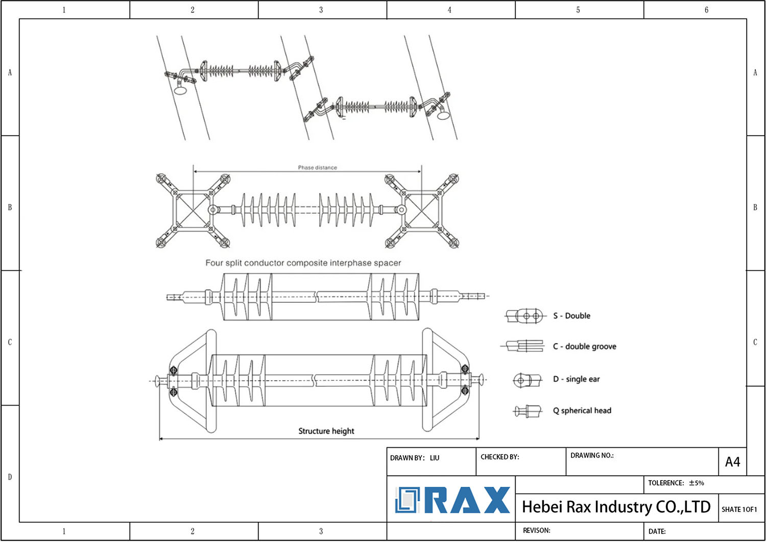
Interphase Spacer Drawing
| Model | Rated voltage KV |
Phase distance MM |
Rated tensile load KN |
Rated bending load KN |
Compression load resistant |
Reverse tolerance to load N.m |
Insulation distance MM |
Minimum nominal creepage distance |
Full wave impulse withstand voltage of lightning strike |
Wet power frequency withstand voltage of |
| IS -66/70 | 66 | 2550 | 70 | 0.4 | 7 | 75 | 2260 | 300 | 410 | 185 |
| IS -110/70 | 110 | 2890 | 70 | 0.4 | 7.5 | 75 | 2600 | 4105 | 550 | 300 |
| IS -220/100 | 220 | 3150 | 100 | 0.4 | 7.5 | 75 | 2820 | 8500 | 1000 | 395 |
| IS -330/160 | 330 | 4650 | 160 | 0.4 | 10.5 | 75 | 4280 | 1180 | 1425 | 570 |
| IS -500/210 | 500 | 5900 | 210 | 0.4 | 12.5 | 75 | 5080 | 14400 | 2250 | 740 |
Related Products
Frequently Asked Questions (FAQ)
What is an Interphase Spacer?
Interphase spacers are segmental flexible, stiff, or integrated flexible insulators designed to maintain conductor separation on transmission lines. They prevent mid-span flashovers caused by galloping and conductor jumping, effectively reducing dynamic loads and galloping amplitude on transmission lines.
What are the main types of Interphase Spacers?
Three main types exist: Stiff Type (traditional, heavy design), Integrated Flexible Type (commonly used, more stable), and Segmental Flexible Type (features segmental structures). Each type offers different benefits for specific transmission line applications.
How does an Interphase Spacer work?
The spacer mechanically connects conductors of different phases, forcing galloping to move in a way that minimizes flashovers. It maintains phase-to-phase clearances at predetermined limits while providing additional damping through flexible composite insulators.
Where are Interphase Spacers typically installed?
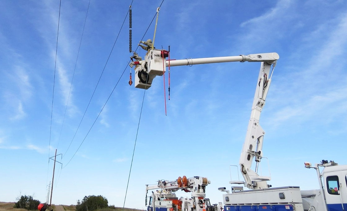 They are installed in middle spans of transmission lines, avoiding symmetrical distribution to prevent standing waves. Installation configurations include Scheme A (for voltages up to 400kV, spans under 500m) and Scheme B (400kV, spans over 500m).
What are the key design features of Interphase Spacers?
Modern spacers feature composite materials for vibration absorption, field-adjustable lengths, modifiable electrical characteristics, and clamping systems. They’re designed to withstand compression loads from galloping and ice shedding oscillations.
What environmental conditions require Interphase Spacers?
They’re essential in areas experiencing severe weather conditions like ice buildup, strong winds, and sandstorms. They’re particularly useful in preventing phase-to-phase contact during ice shedding events and conductor galloping.
What are the electrical requirements for Interphase Spacers?
They must withstand 73% higher power frequency stresses than phase-to-ground insulation due to line-to-line voltage exposure. Key parameters include power frequency voltage distribution, switching impulse flashover voltage, and lightning impulse flashover voltage.
How do Interphase Spacers handle mechanical stress?
They’re designed to handle tension, bending, and fatigue from oscillation. For example, a 275 kV interphase spacer can handle mechanical strength up to 79 kN, with specific designs for tension strength and hardware components.