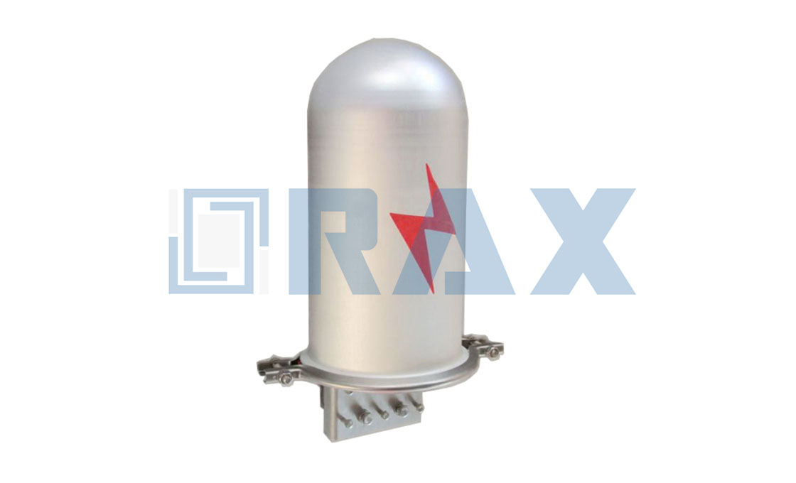
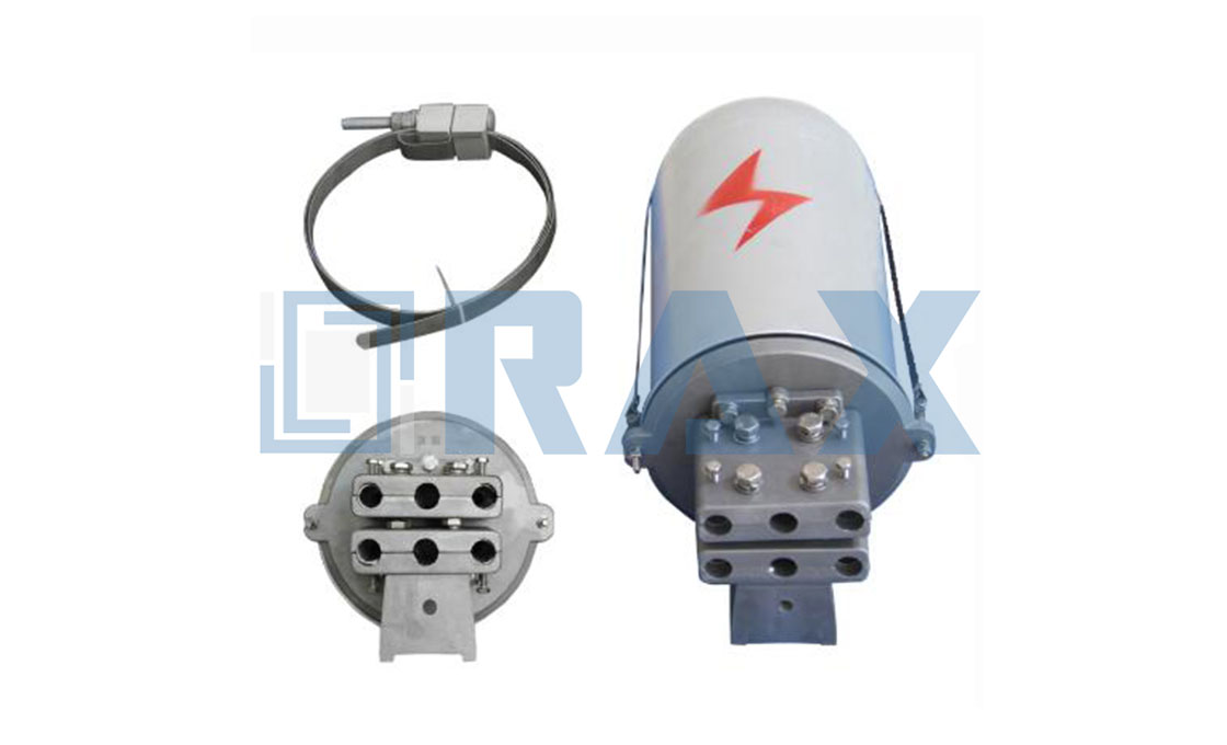
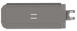
ADSS/OPGW Metal Junction Box
The ADSS/OPGW metal junction box is also called a splicing box that is designed to house the fiber core splices to the outdoor intermediate optical cable leading to the patch panel in the control room. The fiber core splice is to connect the trunk cable(e.g. OPGW)
Rax Industry fiber optic cable junction box has the features as below :
1. Junction boxes support, organize, and protect the optical fibers.
2. Junction boxes ensure that the optical fiber minimum-bending radius is not exceeded.
3. The splice tray has no sharp edges or protrusions that may damage the optical fiber cable.
4. A junction box is rated to IP65 in accordance with IEC 60529.
Junction boxes provide entry for all cables Include number tags for tube and fiber identification. The enclosure is lockable.
Rax Industry Junction box is mounted on a wall or pedestal at a conveniently accessible height.
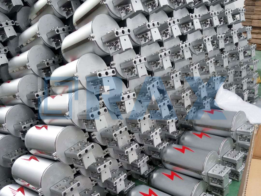
As a professional manufacturer, supplier, and exporter, Rax Industry can support all sizes of Metal Junction Boxes, We can also customize them according to your designs.
ADSS/OPGW Metal Junction Box For Tower:
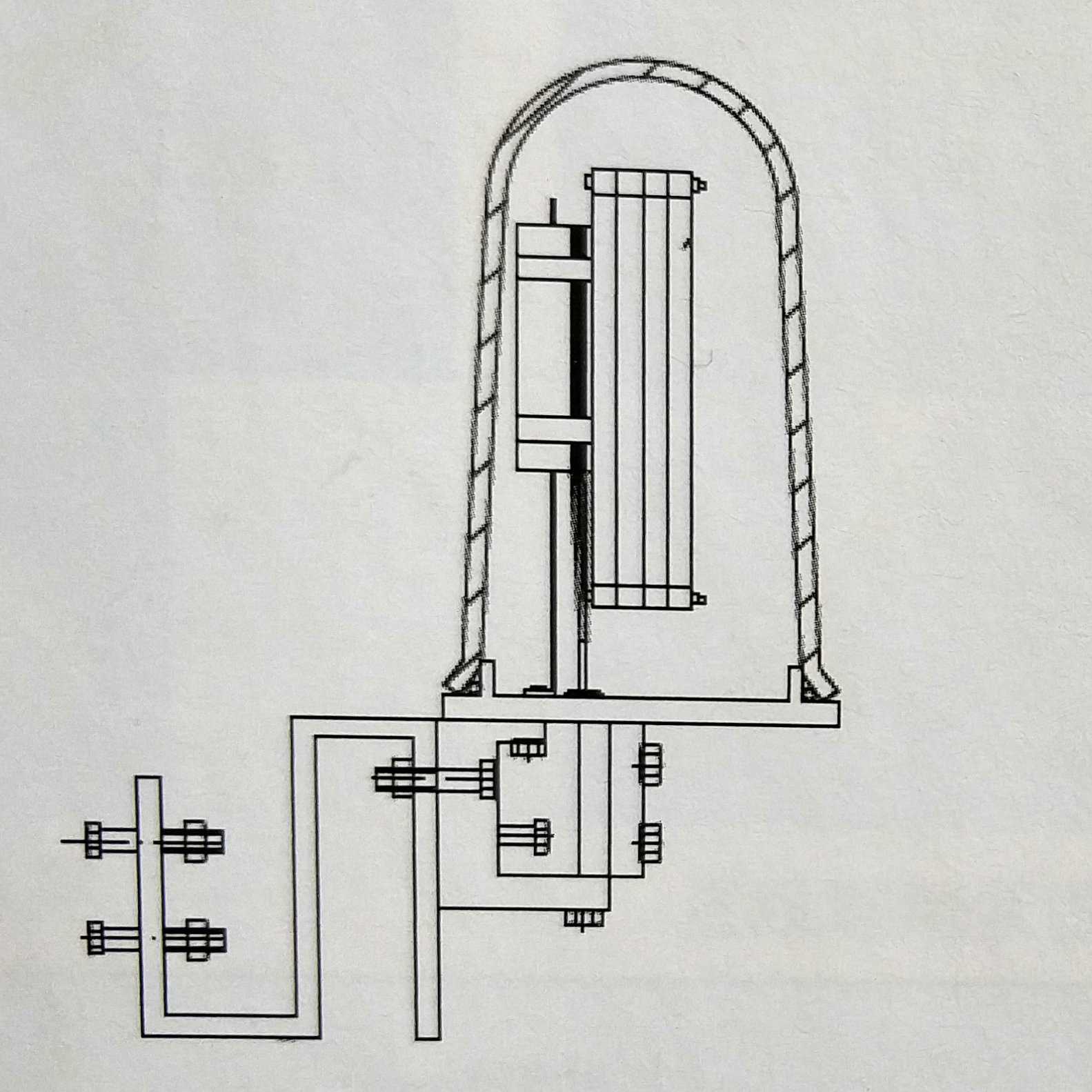
FOR TOWER
| Application | Specification Model | Suitable Range | Weight(kg) | Material |
| FOR TOWER | JTHT-2-012 | Two ports, 12 Fibers | 4.1 | Aluminium Alloy |
| JTHT-2-024 | Two ports, 24 Fibers | 4.1 | Aluminium Alloy | |
| JTHT-2-036 | Two ports, 36 Fibers | 4.1 | Aluminium Alloy | |
| JTHT-2-048 | Two ports, 48 Fibers | 4.1 | Aluminium Alloy | |
| JTHT-2-060 | Two ports, 60 Fibers | 4.1 | Aluminium Alloy | |
| JTHT-3-012 | Three ports, 12 Fibers | 4.2 | Aluminium Alloy | |
| JTHT-3-024 | Three ports, 24 Fibers | 4.2 | Aluminium Alloy | |
| JTHT-3-036 | Three ports, 36 Fibers | 4.2 | Aluminium Alloy | |
| JTHT-3-048 | Three ports, 48 Fibers | 4.2 | Aluminium Alloy | |
| JTHT-3-060 | Three ports, 60 Fibers | 4.2 | Aluminium Alloy |
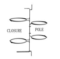
ADSS/OPGW Metal Junction Box For Pole:
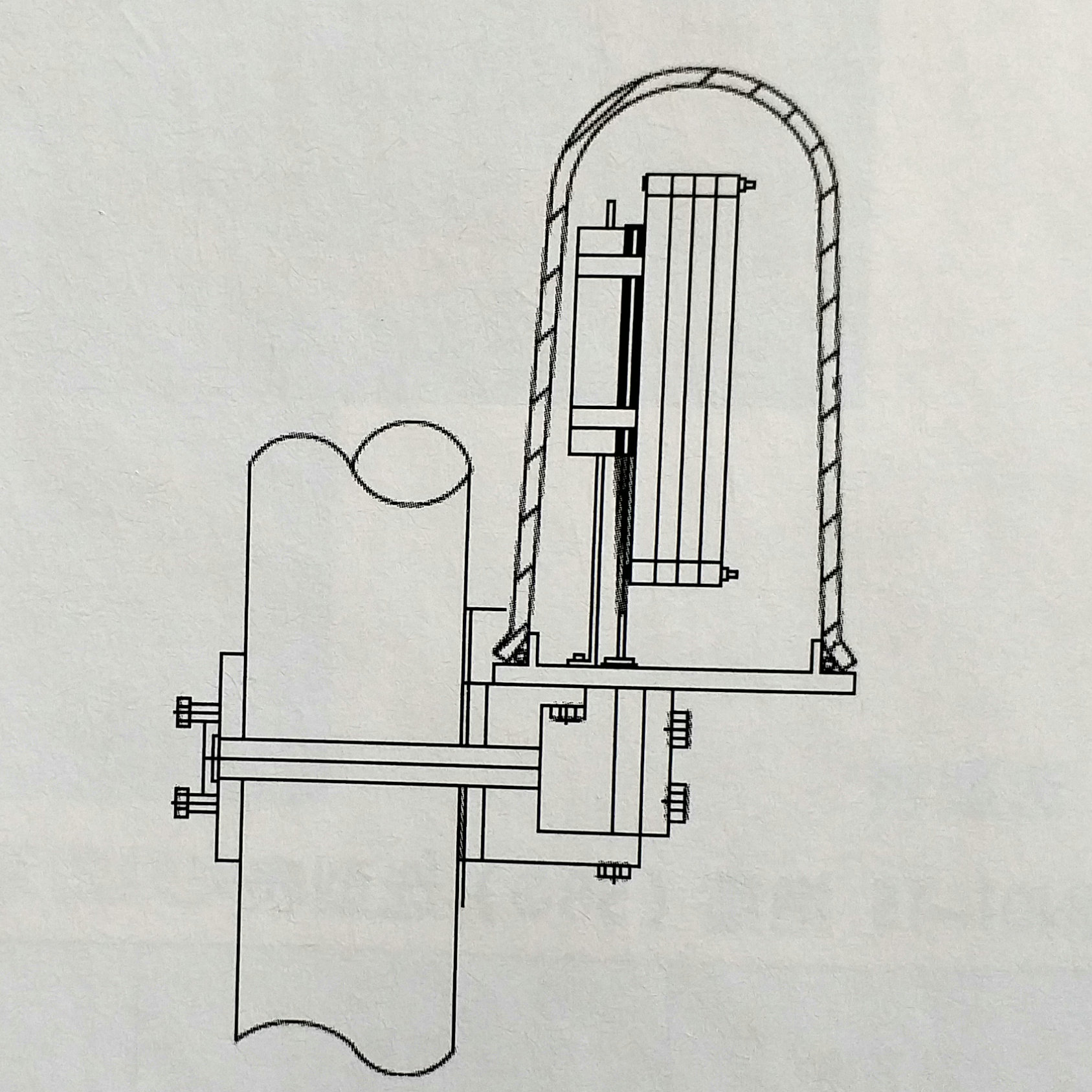 FOR POLE
| Application | Specification Model | Suitable Range | Weight(kg) | Material |
| FOR POLE | JTHP- 2-012 | Two ports, 12 Fibers | 4.1 | Aluminium Alloy |
| JTHP- 2-024 | Two ports, 24 Fibers | 4.1 | Aluminium Alloy | |
| JTHP- 2-036 | Two ports, 36 Fibers | 4.1 | Aluminium Alloy | |
| JTHP- 2-048 | Two ports, 48 Fibers | 4.1 | Aluminium Alloy | |
| JTHP- 2-060 | Two ports, 60 Fibers | 4.1 | Aluminium Alloy | |
| JTHP- 3-012 | Three ports, 12 Fibers | 4.2 | Aluminium Alloy | |
| JTHP- 3-024 | Three ports, 24 Fibers | 4.2 | Aluminium Alloy | |
| JTHP- 3-036 | Three ports, 36 Fibers | 4.2 | Aluminium Alloy | |
| JTHP- 3-048 | Three ports, 48 Fibers | 4.2 | Aluminium Alloy | |
| JTHP- 3-060 | Three ports, 60 Fibers | 4.2 | Aluminium Alloy |

Related Products
A Guide to The Junction Box
Introduction:
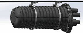
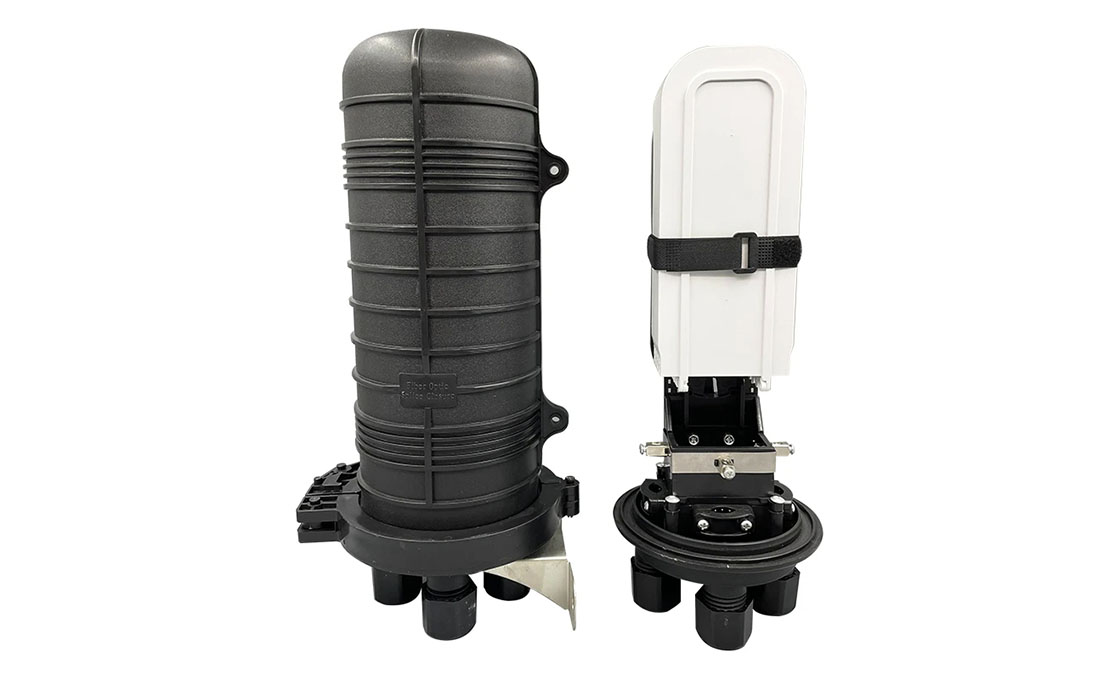
This product is used to connect the distribution cable and the incoming cable is widely applied in communication, network systems, CATV cable TV and so on. It adopts scientifically formulated engineering plastic and be shaped by injection molding, anti-aging, anti-corrosion, flame retardant, waterproof, anti-vibration and anti-shock effects. It can effectively prevent optic fibers from the influence of the outdoor environment.
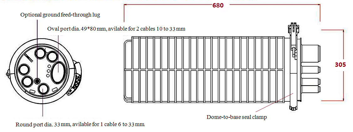
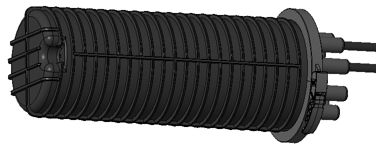
Dome-to-base design; up to 8 pieces splice trays with excessive loose buffer storage basket, hinge for access of any splice without disturbing others trays; Fast and reliable sealing performance, easy to package multiple times. With a lightning protection grounding device, it can be applied in overhead, pole/ wall mounting or directly buried.
Specification:
| Model: | GJS03-M4AX- 576 | ||
| Size: | 680*305 mm | Raw material | Dome,clamp,base:modified PP +GF
Tray: ABS Metal parts:Stainless steel |
| Entry ports number: | 1 oval port, 5 round ports | Available cable dia. | Oval port:available for 2 pcs, 10~33mm cables
Round ports:Each available for 1pc 6-33mm cable |
| Max. tray number | 8 trays | Base sealing method | Heat-shrink |
| Tray capacity: | 72 F | Applications: | Aerial, Pole mounting, directly buried, Wall mounting |
| Max. closure splice capacity | 576 F | IP grade | 68 |
-
Order Guidance:
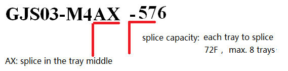
-
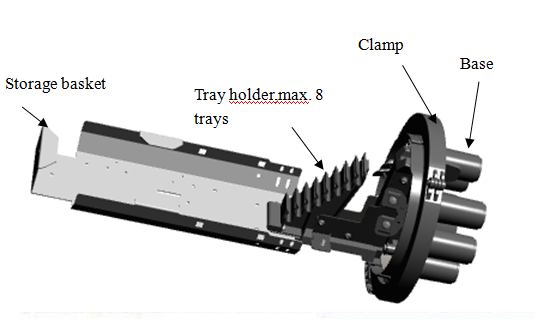
Exterior Structure Diagram
Technical Parameter:
1. Working Temperature: -40 degrees centigrade~+65 degrees centigrade
2. Atmospheric Pressure: 62~106Kpa
3. Axial Tension: >1000N/1min
4. Flatten Resistance: 2000N/100 mm (1min)
5. Insulation resistance: >2*104MΩ
6. Voltage Strength: 15KV(DC)/1min, no arc over or breakdown
7. Temperature recycles: under -40℃~+65℃,with 60(+5)Kpa inner pressure, in 10cycles; Inner pressure shall decrease less than 5 Kpa when closure turns to normal temperature.
8. Durability:25 years
Main components:
| Name | Qty | Picture | Name | Qty | Picture | ||||
| Dome | 1pc | 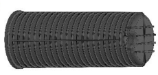 |
Tray | Max. 8 pcs | 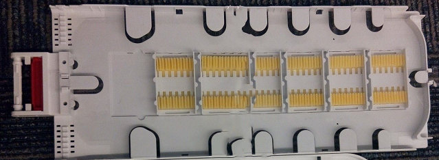 |
||||
| Clamp | 1pc | 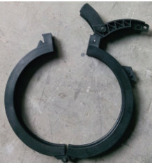 |
Valve | 1 | 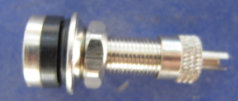 |
||||
| Base | 1pc | 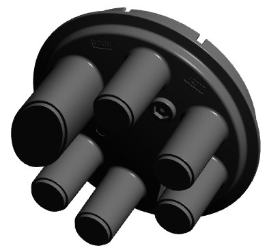 |
Modified O-ring | 1 | 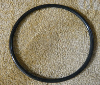 |
||||
| Cable Strengthen member attach plate | 1set | 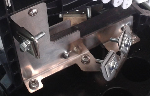 |
Velcro strip with one X flake | 1 | 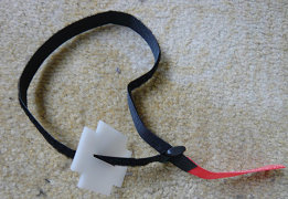 |
||||
| optic joints protection tube | Max. 576 | 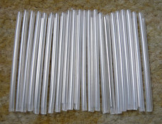 |
Ground feed-through lug | 1 | 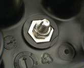 |
||||
| Nylon tie | 12pcs/bag | 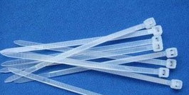
Max. 4 bags |
Transparent PE tube | 8pcs/bag
|
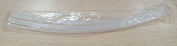
Max. 4 bags |
||||
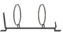
| Metal Storage basket | 1 Offer based on splice capacity | 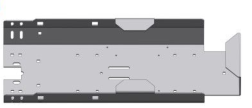 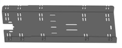
|
|||||||
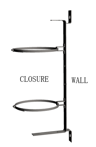
| Wall mounting kits | 1
Standard offered with |
 |
|||||||
| Aerial mounting kits | Order as optional | 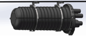
|
|||||||
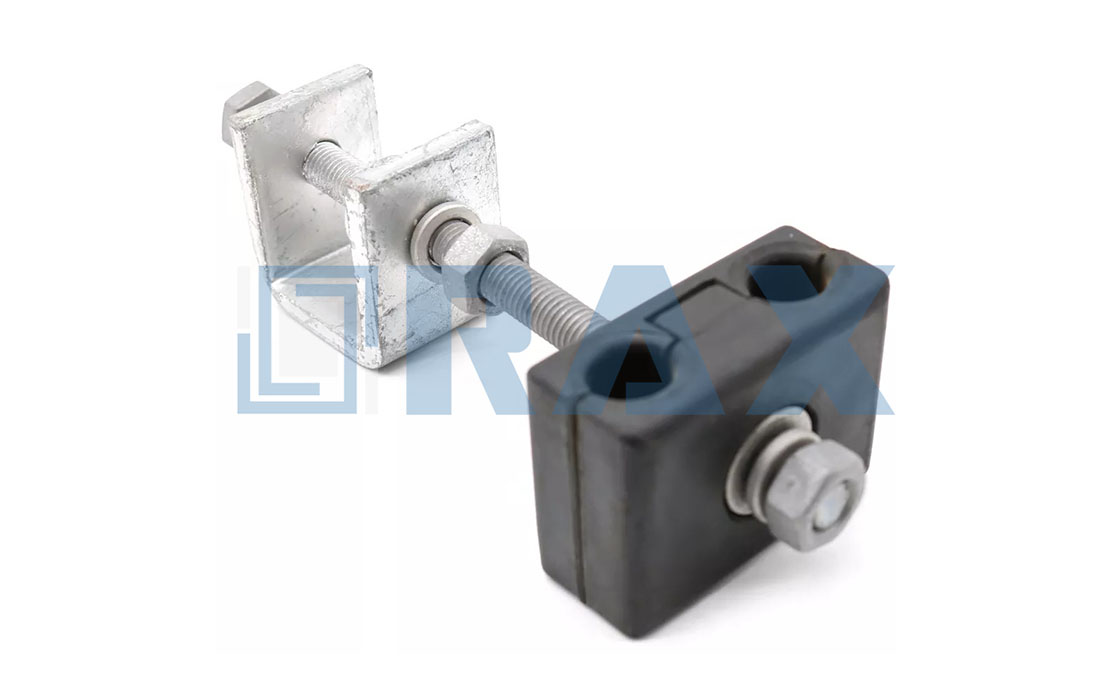
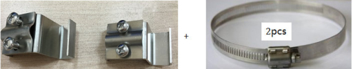
| Pole mounting kits | Order as optional | 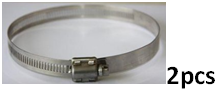 |
|||||||
| Round Port accessories bag | 1 bag | 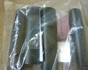 |
Items | Heat-shrink tube | 5 |  |
|||
| Abrasive tape | 1 |  |
|||||||
| Aluminium foil | 5 | 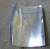 |
|||||||
| Oval port accessories bag | 1bag | 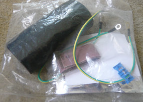 |
Items | Heat-shrink tube | 1 | 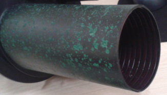 |
|||
| Abrasive tape | 1 | 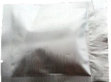 |
|||||||
| Aluminium foil | 2 | |
|||||||
| Cleaning tissue | 1 | |
|||||||
| Desiccant | 1 | 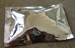 |
|||||||
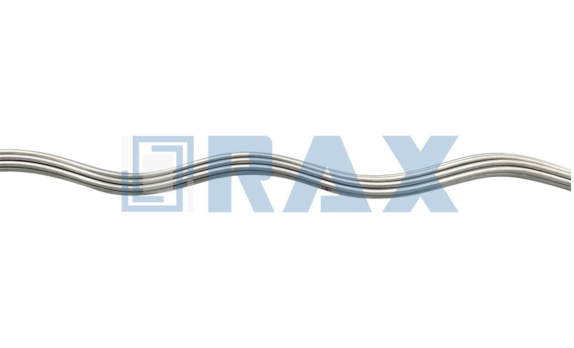
| Shield continuity wire | 1 | 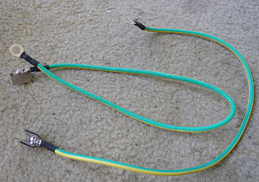 |
|||||||
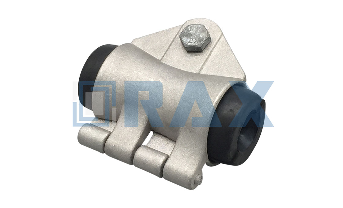
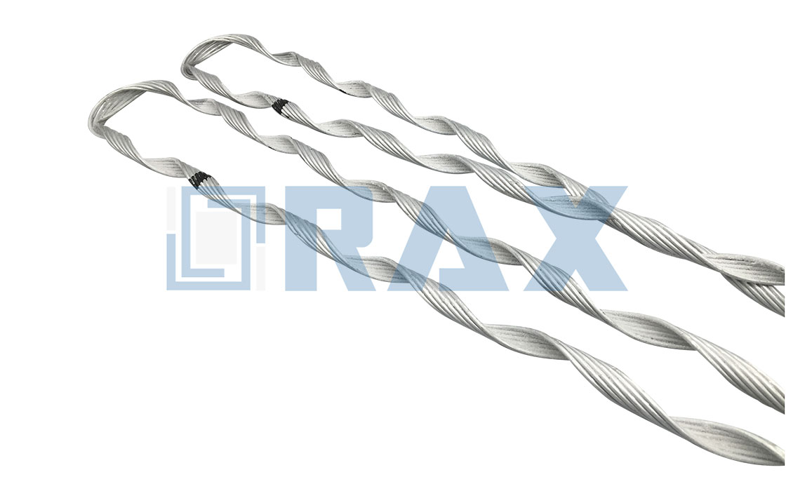
| AMP clamp | 1 | 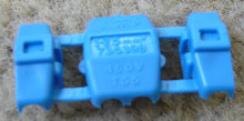 |
|||||||
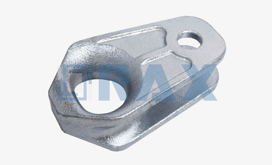
| Branch off clip | 1 | 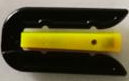 |
|||||||
Installation Guidance
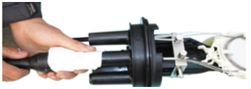
1. Cut the ports need to guide-in cable.
2. Put the cable through the heat-shrink tube
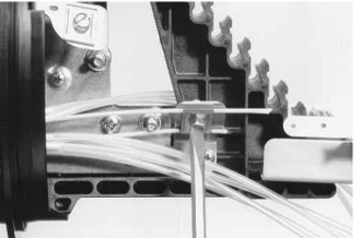
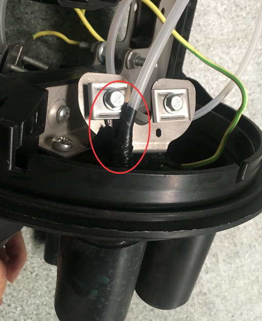
3. Remove the sheath of the cable and clean it. Cut the strengthen member to 5cm length. Put it through the attach screws and bend it to fix on the screw. Then tighten the screw.
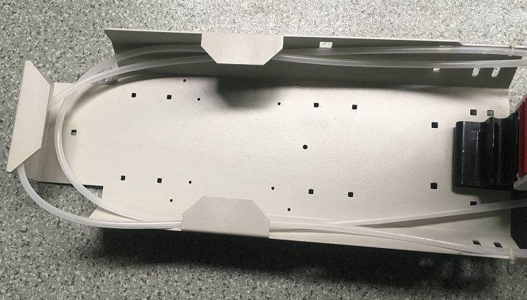
4. Remove the loose tube of the cable and clean the bare fibers. Put them through the transparent PE tube. Using PVC tape to wrap the end of the PE tube and cable.
5. Wind the excessive loose buffers in suitable cycles and put in the storage basket.
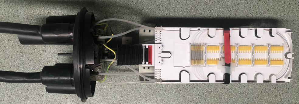
6. Coiling the optic fibers in the splice trays as above picture from the bottom tray to the top one. Fusion the joints and shrink the protective tubes and fix them in the tray. And put on the tray lid.
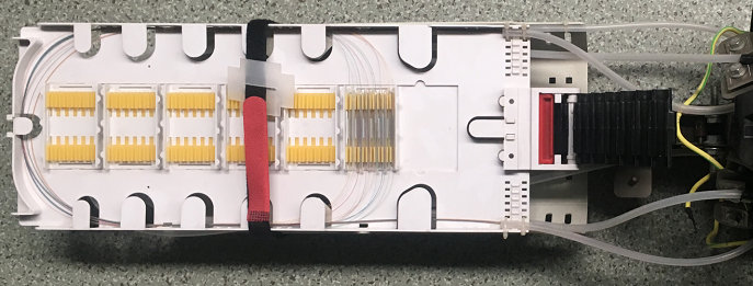
7. Use the Velcro strip to bind the trays.
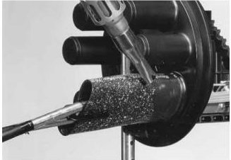
8. Using abrasive strip to rough the surface of the cable sheath and ports slightly.
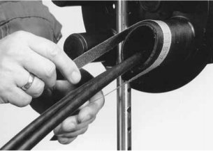
9. Clean the cable surface and ports.
10. Move the heat-shrink tube to cover the base port and the cable. Mark the tube end on the cable and stick the aluminum film on it. The blue line of the film shall at the same position of the marked place. ( Edge which closes to the blue line shall be in the tube. Other side out of the tube.) Using a blunt tool to even the film tightly stick to the cable. Heat the tube to shrink to seal from the direction of the red arrow slowly. (If to guide 2 cables in the oval port, use branch off clips to separate the cables, heat the branch off clip at the meantime to seal the space.)
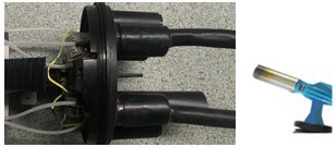
11. Heat the round ports follow the same step as the oval port.
12. Close the closure with the clamp.
13. Choose the suitable mounting kits for the different installation environment.